Breakout Board for the ESP32-C3-WROOM-02 Wifi Module
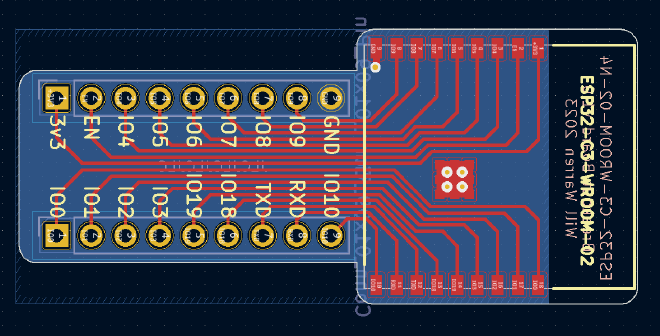
Table of Contents
🥳 Update: You can now buy the boards premade from my Tindie store: https://www.tindie.com/products/33043/.
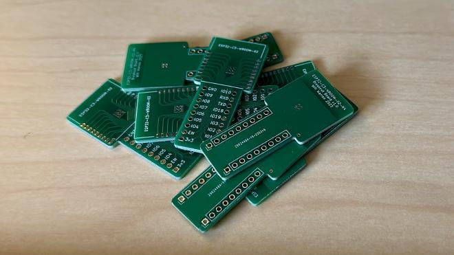
Similarly to my previous project for the ESP-12E/F modules, I wanted to be able
to experiment with the ESP32-C3-WROOM-02-N4 module. The pitch of the
castellated pins on the module makes breadboarding difficult, so I created a
very simple breakout board in KiCAD.
Note: throughout this post I talk about the 02 version of this module, but
this breakout board would work totally fine with the 02U variant (without the
PCB antenna).
After designing the PCBs in KiCAD I sent them away to JLCPCB to fabricate.
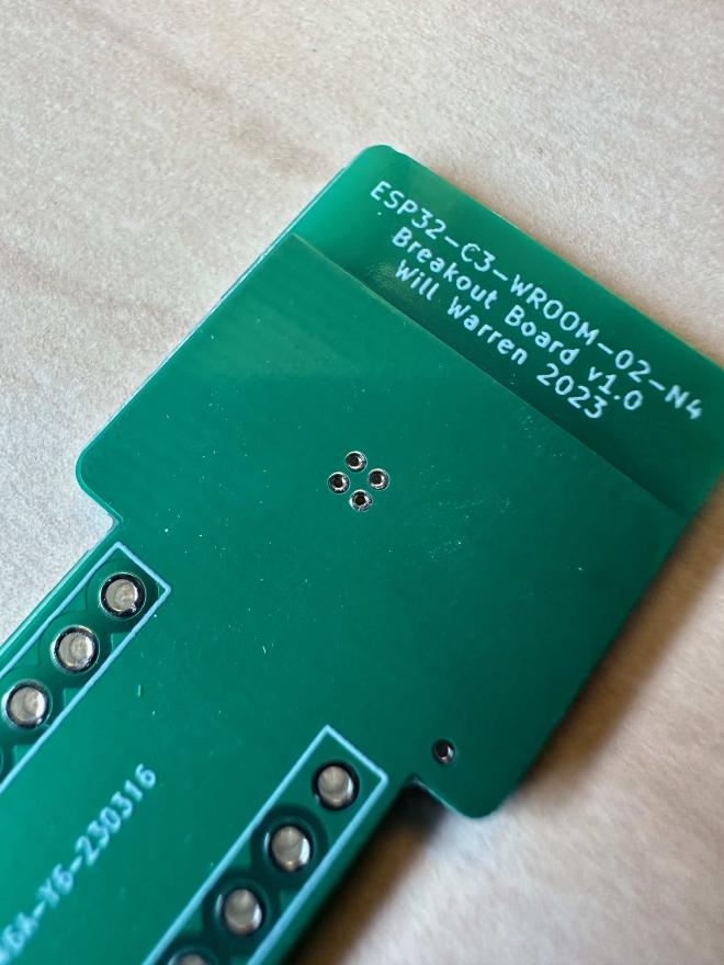
One specific option I chose when ordering the PCBs was untented vias. This allowed me to solder the EPAD under the module more easily (from the bottom). Still, I wouldn’t recommend this, and would suggest using a hotplate or reflow oven instead.
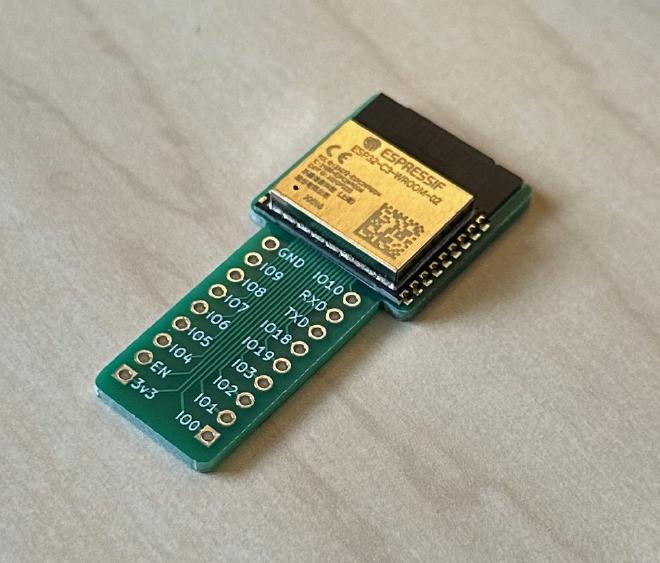
After assembly the boards work great!
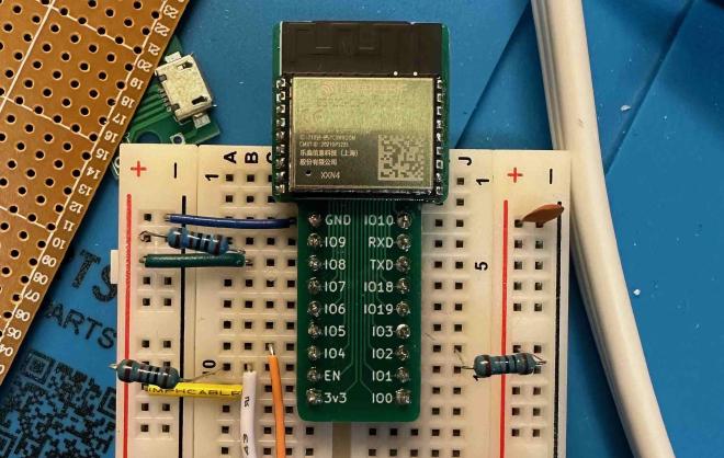
Get the board! #
🥳 You can now buy the boards premade from my Tindie store: https://www.tindie.com/products/33043/.
Alternatively, you can have your own boards fabricated from your preferred PCB fab manufacturer using the KiCAD files from Github! The files can be found here: https://github.com/phybros/esp32-c3-wroom-02-n4-breakout.
Hopefully this can be helpful to fellow tinkerers!
Bonus Janky Dev Board #
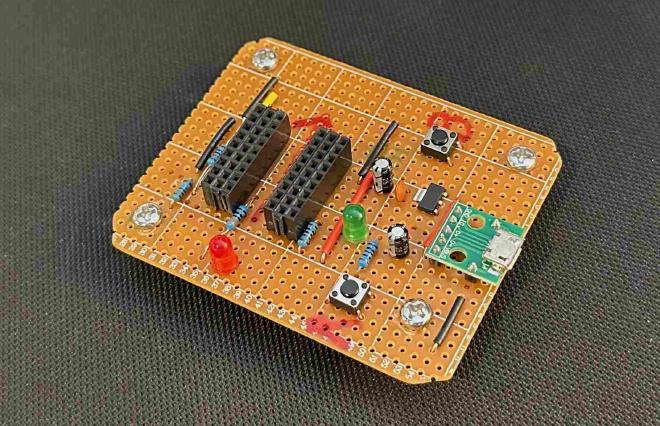
I made this “dev board” very quickly with parts I had laying around. Features:
- All the required strapping pins
- Micro USB connection for power AND programming
- 3.3V regulator (legs shoved violently into the perfboard in defiance of nature)
- LED on GPIO4
- Power LED
- “Breadboarding area” made of pin sockets
I just slotted one of the breakout boards into the middle “socket” and away I went! I recently used this exact board to prototype a new smart Garage Door opener! More on that in a later post 😉.
